3D laser cutting offers expanded opportunities but requires adequate technical solutions to obtain the desired quality and robustness of results.
The first laser for industrial applications appeared in 1964, emitting just 1 milliwatt (mW). By 1967, lasers with power exceeding 1,000 watts and the capability of cutting 1 mm thick steel sheet was possible. That is one million times more powerful than the first model!
Right from the start, the effectiveness of the laser in melting the metal made use of the aid of a service gas blown through a nozzle thereby removing the layers of molten metal hit by the light energy emitted by the source.
Find out more about laser cutting origins
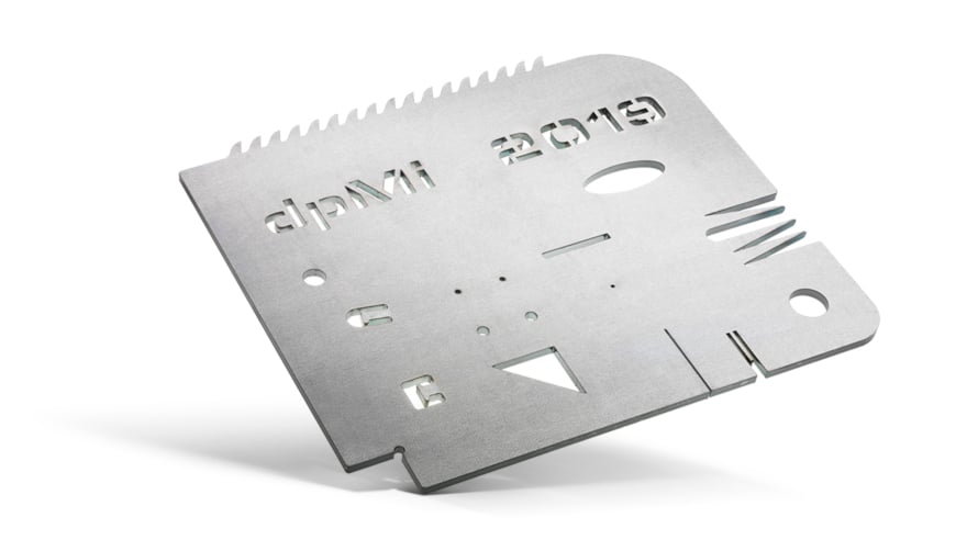 Test piece cut with LS5 sheet laser cutting system. The dynamic control of the cutting parameters and the position of the focus allows the system to maintain the same cutting quality regardless of the complex geometry of the part: holes less than the sheet thickness, very thin cuts and cusps.
With the increase in power, over the years, the cutting thicknesses has increased to over 50 mm of steel with a 10 kW system.
Initially, the service gas was compressed air. Subsequently, oxygen was used for the oxidation reaction which significantly contributed to the heating and melting of the metal, enabling the melting of thicker materia.
Even more recently and with the increase in available power, nitrogen - an inert gas that does not contribute to heat generation - is widely used due to its characteristic of not thermally and chemically altering (oxidizing) the cut surface.
The advantage is machined parts can be painted directly without the need of further preparation.
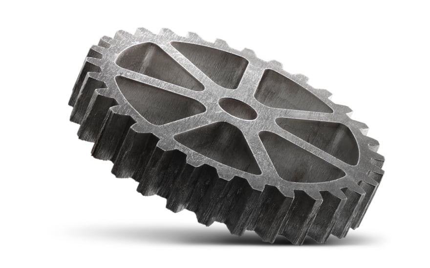 Gear made with the LS5 sheet laser cutting system.
With respect to the entire manufacturing process, cutting cost is higher with nitrogen since nitrogen is more expensive than oxygen and requires much greater power to be used to maintain the same maximum workable thickness. Therefore, a higher initial investment will affect the hourly cost of the system and production costs.
The benefits of either choice can be assessed by using Protube software -the precise estimation tools of production times and costs. Manufacturers using laser cutting systems consider Protube to be an essential everyday tool.
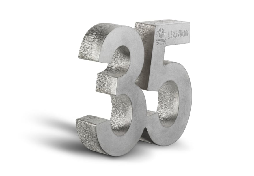 Steel part from 35 mm thick steelwork, cut with a sheet laser cutting system using an 8 kW source.
Whether it is cut with compressed air, oxygen or nitrogen, in all cases, efficiency and quality of the result are connected to the way in which the assist gas is blown into the cutting groove: supplied pressure, but above all flow conditions. The more the gas maintains a linear flow with as little turbulences as possible, the more efficient the ejection of the molten metal from the cutting groove and consequently the quality of the cut itself.
With thick materials, the gas flow must penetrate deeply - in a narrow groove - and its flow inevitably becomes turbulent, before being ejected from the opposite side together with the molten metal. In recent years, technical solutions have been introduced to improve the process by widening the cutting groove to facilitate assist gas input and help to obtain the best linear flow possible.
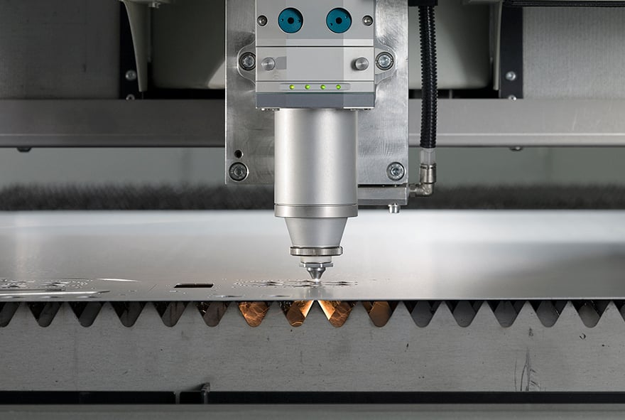 Laser cutting head of LC5 flat-sheet & tube laser cutting system.
So far we have not specified from which direction the laser beam acts with respect to the cutting surface. The best possible direction is orthogonal (perpendicular) to the surface. In this configuration, the gas flow is centred and penetrates best into the cutting groove. There are no preferential sides nor pressure unbalancing effects due to turbulences around the groove, caused by the part of gas that cannot enter and therefore hits the immediate surrounding area. This is the configuration of all sheet metal cutting machines with rare exceptions. The laser moves on a flat, bi-dimensional (2D), surface and always cuts perpendicular to that surface.
The need to cut increasingly greater thicknesses at higher cutting speeds has been resolved over time with gradually increased power and with the ability to increase the laser beam diameter and therefore the groove width. Together this facilitates the assist gas performance and finishing of the cut edges.
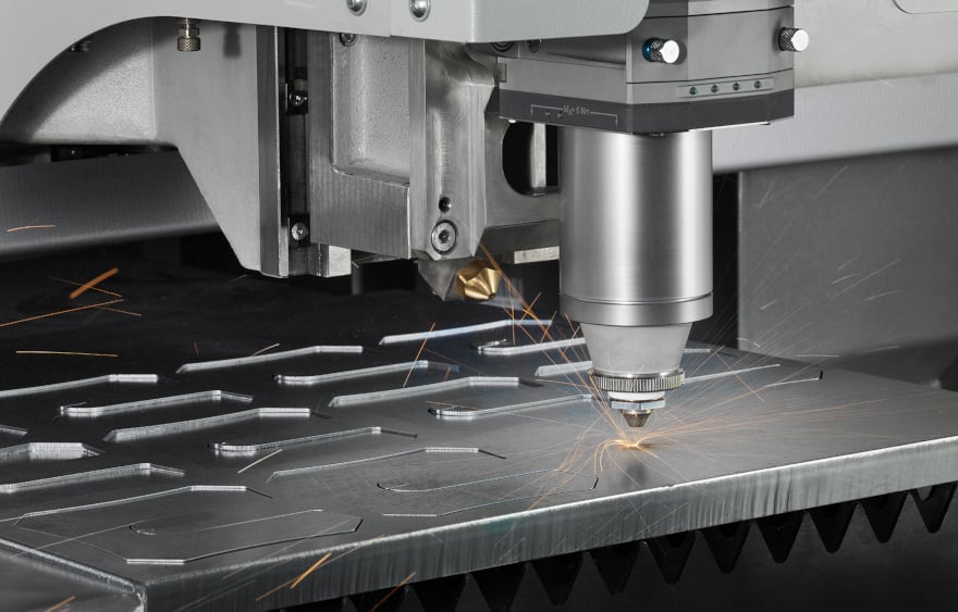 Laser cutting of a metalwork sheet carried out with LS5.
Now, let’s move from sheet to tube cutting: the situation changes considerably. We are no longer faced with planar cutting trajectories but with a movement of the laser in space around an object- its thickness, and a profile including radii and edges, convex surfaces and concave angles, the later typical of the special sections.
The variation of the configuration between laser beam and tube surface has consequences on the cutting process and needs to be taken into account in order to ensure process efficiency. Therefore, the nozzle distance, focus position (where dynamically adjustable), the power required by the greatest thickness present, in correspondence with the radii, and consequently also the cutting speed, must constantly change. All this must work together to prevent burnt spots and cutting loss.
Find out more about the diffusion of metal tubes in manufacturing
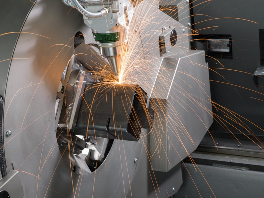 Tube laser cutting carried out with Lasertube LT8.20 system.
To these factors we add the possibility to cut by tilting the head, so that the beam hits the surface in a non-orthogonal direction. We know this as 3D laser cutting.
This additional machining option present in machines equipped with a tilting head is especially useful for machining higher thicknesses. With the 3D cutting it is possible to make cuts with an angle up to 45°. For example, to obtain precise supports among several tubes or “chamfered” cuts to facilitate the subsequent welding phase because they create the space for the weld material. Even more challenging, but increasingly used, is the application of welding without filler material, possible when distance between edges to be welded is reasonably precise and constant.
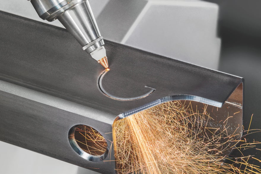 Chamfering with LT7 laser cutting system.
However, such cuts pose difficulties and require specific technical solutions. The ability to tilt the head with respect to the surface to be cut in 3D causes the actual cut thickness to become greater than the nominal one, to a maximum bevel cut of 45 degrees, an angle at which a laser penetration depth must be taken into account and that of the assist gas which should be multiplied by square root of two.
It is also necessary to change the focus position, which poses an issue on parts with mixed 2D and 3D geometries. If focus position can be adjusted dynamically, all cases can be effectively covered by changing the focus height from one geometry to the other, otherwise it will be necessary to pre-configure a compromise focus height, with the consequence of a performance reduction in terms of cut quality or productivity.
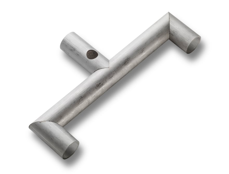
 Tubular part obtained with laser.
A further but significant effect of head tilting is the resulting geometrical inaccuracy of parts, unless suitably managed. The “kerf” that is the beam diameter and correspondingly therefore the width of the cutting groove, vary in function of the angle of incidence. This is a direct result of the shape of the laser coming out of the cutting head being conical and not cylindrical, thus determining the different imprint as tilt varies.
This parameter must be compensated for otherwise the part length will be altered and will not tightly align when matched to another part, thus hindering welding without filler material or jeopardizing the aesthetic result in the most critical cases.
The cut quality is affected by the manner the assist gas enters the cutting groove.
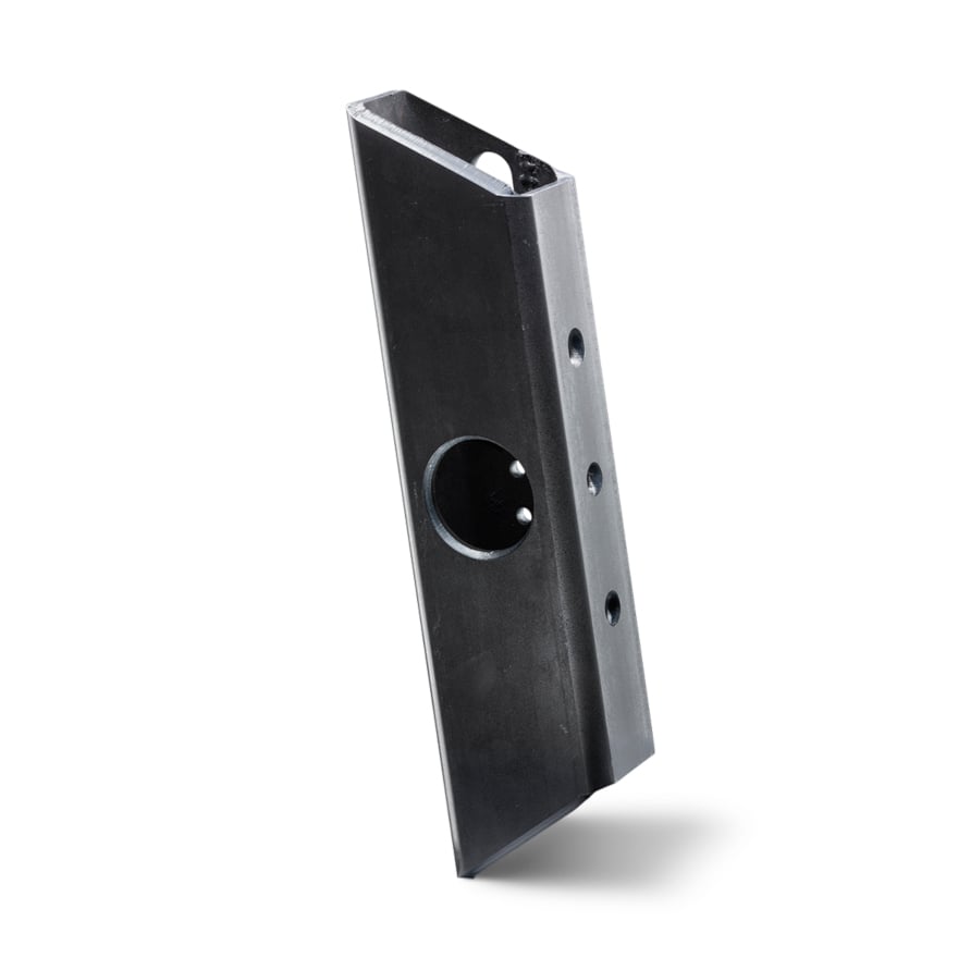
 Support made between laser cut steel tubes.
As cutting inclination increases to the limit of 45 degrees with respect to the vertical plane, the gas meets the surface at an angle which is greater on one side compared to the other. On one side (obtuse angle) the gas will tend to slide on the tube surface instead of entering the groove, whereas on the other side (acute angle) it will trigger a greater turbulence. As a result, the gas will be less efficient and the process less stable.
Finally, let’s consider a last but no less important factor in 3D laser cutting- tube shape errors and tube axis deformation, either pre-existing or induced by the cantilever position of the tube during cutting. When the tube can be supported vertically during machining and measured to compensate for errors due to existing deformations, more precise parts will be obtained. Conversely, without these measures, wider tolerances and the expectation of higher reject numbers is to be expected.
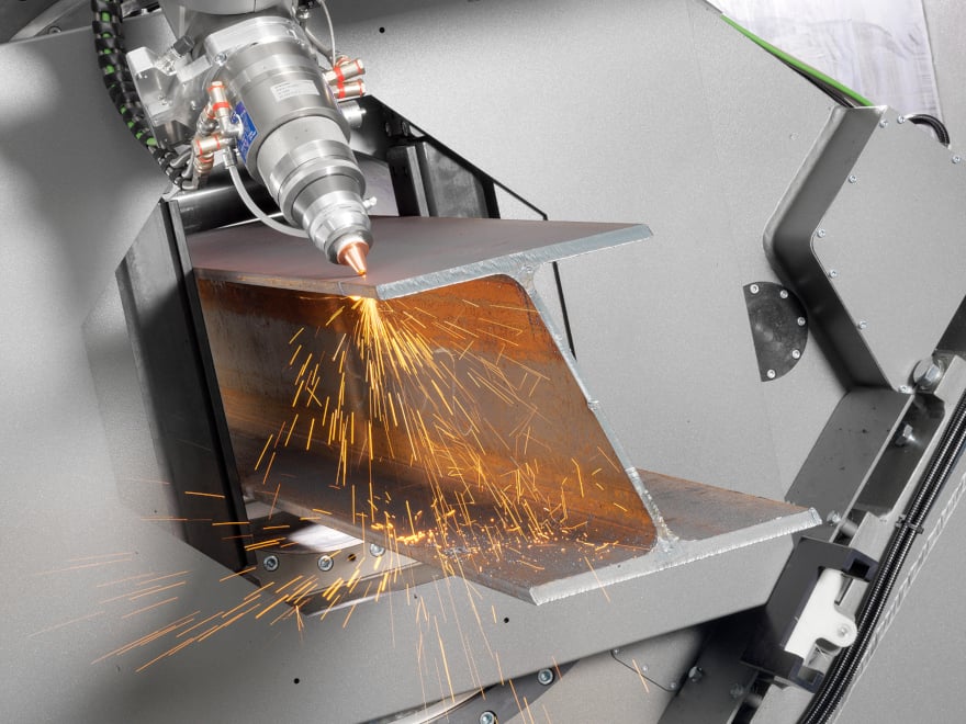 Laser cutting of an “HEA” beam with LT14 laser-cutting system for large tubes and profiles.
So far we have learned what 3D laser cutting means, what advantages it offers and also the many technical aspects that must be managed in order to maximize the benefits this machine option has to offer. The experience and technical solutions integrated into the BLM GROUP Lasertube systems, provide our customers with a company that has been producing tube laser cutting machines for over 30 years and in 2003 were the first to introduce 3D cutting on a Lasertube. As the industry leader, we are a good starting point if you are evaluation of this option, in addition to the mechanical configuration of the machine which, however necessary, is not sufficient in itself to ensure the financial return of the greater investment required.
3D cutting - albeit constantly evolving - is a machining process not yet in widespread use but appreciated in specific sectors: where there are aesthetic needs in cutting thin materials, or where cost reduction targets are pursued in creating high thickness steel structural frame metalworks Investing in this direction means moving towards potentially interesting market niches with high added value. It is therefore worth relying on an experienced partner to assist you in evaluating the advantage of the investment, calculate risk margins and define a payback period.