Manufacturers are continually looking for ways to eliminate waste in their manufacturing process and save cost. Tube fabricators are no different. This becomes even more evident when multiple tubes are required to build an assembly.
One of the most cumbersome challenges faced by tube fabricators is the joining of tube components. Difficulties are often encountered with fit-up, fixturing and assembly.
This is especially true when secondary process operations, such coping and mitering, are required after the bending process.
Take the following as an example: a high-end fitness equipment manufacturer develops a new aerobic product, which we’ll refer to as STEP. The complex assembly is comprised of nine stainless steel tubes varying in length; one main tube and eight individual sections. It requires coped tube ends to be welded to the side of a common bent tube.
The plant is equipped with both older technology -- which offers a lower machine rate/hour, as well as state-of-the art tube processing equipment. The manufacturer needs to determine the most cost-effective method to produce the product.
If employing the older equipment, the manufacturer would need to process nine tubes individually to the specified geometries. Total bending time would be about 3 minutes (table 1).
After each tube has been bent, the parts would each need to be positioned in a complex fixture for the coped milling and miter saw processes. As shown in table 2, to cope and saw the nine parts would take approximately 4.4 minutes.
To optimize fit-up requires a fixture of higher complexity, in turn increasing fixture costs. Although the machine cost per hour is lower, this approach will increase labor time, material consumption, and likely result in a higher cost per produced assembly.
| Part | Process time | Handling time | Number of parts | Total cycle time |
| Common tube | 21 s | 6 s | 1 | 27 s |
| Two bent parts | 15 s | 6 s | 6 | 126 s |
| Single bend parts | 7 s | 6 s | 2 | 26 s |
| Total bending time | 2.98 minutes |
Table 1: Cycle time analysis using older bending machine.
| Part | Coping process time | Miter process time | Handling time | Number of parts | Total cycle time |
| Common tube | 0 s | 10 s | 12 s | 1 | 22 s |
| Two bent parts | 10 s | 5 s | 15 s | 6 | 180 s |
| Single bend parts | 10 s | 5 s | 15 s | 2 | 60 s |
| Total cope & mitering | 4.4 minutes |
Table 2: Cycle time analysis for coping & mitering processes.
If the plant decides to produce the parts on the newer machines, the process can be simplified and accomplished more efficiently starting with a Lasertube system -- the most effective solution for coping. The assembly CAD model can be imported into the Lasertube programming software, where it is broken down individually into each of the nine tubes and identifying the cut features for each.
The assembling software then creates a nest based upon the combination of tubes. In this instance, the complex assembly is optimized from nine to three sticks of material. The programmer, with a couple of mouse clicks, can quickly optimize the assembly with the addition of tabs, slots, and micro-tabs to simplify the assembly process and minimize fixturing requirements.
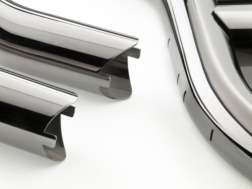 Figure 1: By incorporating tabs and slots to connect the components, the final assembly process is simplified and part fit up is improved.
Before cutting, variables like stretch and spring-back need to be considered as part of the coping and bending processes. With older equipment, to identify these factors using newer technology, a program is generated at the bending machine that incorporates a shallow, medium, and deep bend from a sample stick of the stainless steel at a known length. The bent sample is then measured to identify how much spring-back and stretch occur during the forming process (figure 2). If part tolerances are critical, the evaluation should be performed each time the material batch changes to accurately understand compensation requirements.
Discover how VGP3D programming software simplifies the tube bending process
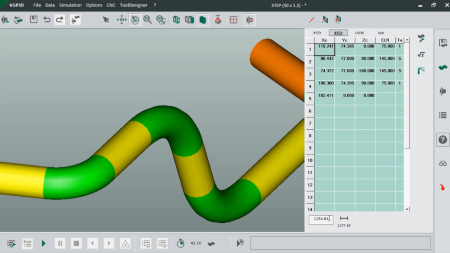 Figure 2: The bent sample is then measured to identify how much spring-back and stretch occur during the forming process.
The data would be stored for use by both the laser tube and bender software programs.
The laser tube operator then incorporates these stretch and spring-back characteristics to the cutting program, which will automatically compensate for these factors ensuring each tube is cut to the appropriate length. The material is now ready to be cut into the three lengths, requiring approx. 1.5 minutes (table 3). When compared to the coping and sawing process, the productivity increase is about 3x faster.
| Part | Process time | Handling time | Number of parts | Total cycle time |
| Common tube | 22 s | 3 s | 1 | 25 s |
| Two bent parts | 28 s | 3 s | 4 | 31 s |
| Single bend parts | 28 s | 3 s | 4 | 31 s |
| Total laser cutting time | 1.45 minutes |
Table 3: Cycle time analysis for laser tube cutting process. The number of parts is no longer a multiplying factor as the parts are being cut from a complete stick of material.
From cutting, the tubes go to the bending process, which is most effectively achieved with an all-electric, multi-axis tube bending system with CNC control. The original CAD model is imported into the tube bending programming software and the compensation data is merged with the program. Remember there are nine parts to be processed, but now only three sticks of material.
By sequencing the bend programs, the parts will be produced sequentially, yielding all of the components needed for the STEP assembly.
The cycle time to process the three tubes is 1.6 minutes (table 4), doubling the productivity. With minimal effort, the micro tabs between each component can be broken to individualize them and prepare for the next manufacturing phase.
| Part | Process time | Handling time | Number of parts | Total cycle time |
| Common tube | 26 s | 6 s | 1 * | 29 s |
| Nest 1 | 31 s | 6 s | 4 * | 34 s |
| Nest 2 | 30 s | 6 s | 4 * | 34 s |
| Total laser cutting time | 1.6 minutes |
Table 4: Cycle time analysis for laser tube cutting process. *The number of parts is no longer a multiplying factor as the parts are being cut from a complete stick of material.
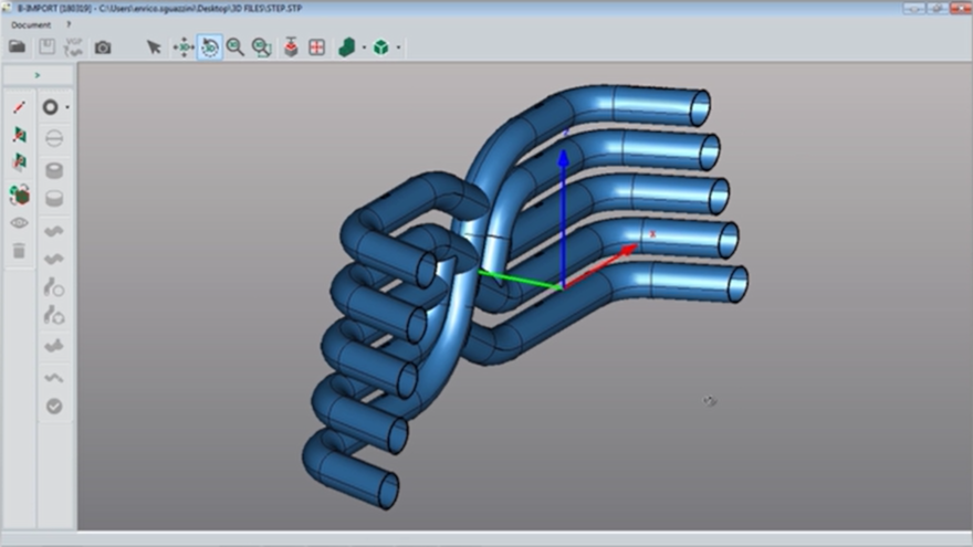 Figure 3: STEP model imported to the machine programming software.
So, overall the entire processing time is reduced from 7.4 to just over 3 minutes, not accounting for the time required for material handling and fixturing. Even if the new equipment bills out at a much higher machine rate/hour, the time and labor saved will deliver a lower cost per assembly.
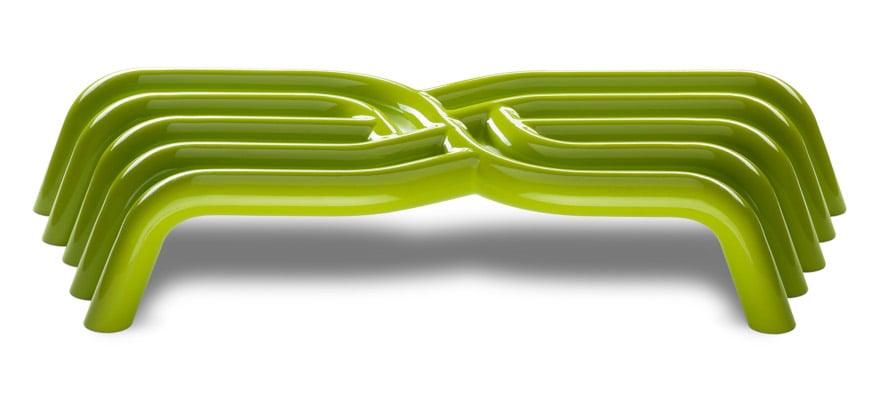 Figure 4: Finished STEP product.
When determining the best way to manufacture complex tube assemblies, consider the big picture and what the overall impact will be.
An older machine with a lower rate cost per hour may achieve short term savings, but in the long term the total manufacturing costs will be higher.
Advancements in machine, CNC control, and offline CAD/CAM software capabilities allow manufacturers to have greater process control, improved productivity and material utilization, in turn boosting profitability.
Source: Fabricating & Metalworking