When you think of tube, normally you think of it as a fluid carrier – a water pipe, a gas line or a fuel line. You don’t think of a tube as a structural element, even if we see several examples of tube being used as a structural element in our daily lives.
You find these examples in modern indoor and outdoor furniture starting from the many types of chairs, school bench structures and table legs.
We also see tubular structures in the constructions: supporting the roof that one can see in airports, railway stations, etc. Similar tubular structures are also used in the industrial sector including machine frames, various structures within agricultural equipment and cranes, etc.
Fabrication of a tubular frame is not a simple process. It becomes more challenging if two tubes are not meeting each other at 90°. This challenge becomes more difficult if more tubes meet at the same point and/or the cross-sections of the meeting tubes are different. If one uses the conventional fabrication method, it involves multiple steps and a variety of machines. Let us use the example of a tubular frame shown in the drawing below and examine the conventional manufacturing process
.
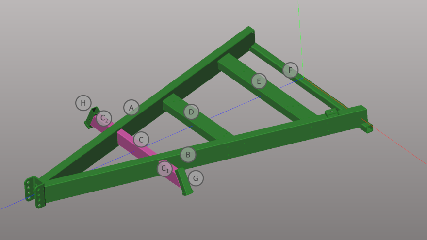 3D sketch of the tubular frame to be produced.
The conventional manufacturing process of the tubular frame
The operations to be carried out on each of the tubes are as follows:
-
Tubes A and B – End cuts on the left side and milling at the other end to accommodate the square tube F. Milling of two groups of 4 holes each.
-
Tubes C, C1 and C2 – The three tubes would require end cuts to match the tubes A and B at an angle. Tubes C1 and C2 would require end cuts at an angle to properly weld tubes G and H.
-
Tubes D and E – Angular end cuts to match with the tube A and B.
-
Tubes F, G e H – Cut to length operation.
For all these tubes, the following process steps will have to be carried out:
- Measuring
- Marking
- Saw cutting
- Milling
- Deburring
Some of the tubes in fact require a secondary drilling process to be carried out that will again involve measuring and marking before drilling.
The processes mentioned above require multiple machines, skilled manpower, time and effort. Despite all these, the tube-to-tube fitment may not be ideal because these processes have inherent limitations in terms of accuracy and repeatability.
Once the tubes are ready, a welding fixture is required to hold all the pieces together for welding. If the joinery does not have good matching surfaces, robotic welding of the tubes cannot be used and one must carry out manual welding. In this case, all the gaps will need to be properly filled (meaning extra consumption of welding wire, time and energy).
The manufacturing process of the tubular frame with a Lasertube
Now let us see how you would manufacture this frame using BLM GROUP’s Lasertube machine.
Il primo passo è quello di importare il disegno 3D dell'intera struttura nel software di programmazione e simulazione CAD-CAM off-line Artube.
The first step would be to import the 3D drawing of the entire structure into the off-line CAD-CAM programming and simulation software Artube.
Once the drawing is imported, with one click, the software will process the drawing, identify each of the tubular components, determine the cross-section dimensions, identify the cutting to be performed and generate the machine programs for the laser cutting of each tube. Once the drawing is imported into ArTube, it can be treated as if it was created using it; you can apply all the features that are available in ArTube to each tube to facilitate assembly and welding.
This is a very powerful functionality because one can modify the single components and add special joinery configurations, even if those were not originally designed. For example “Tab and Slot” or tube to tube joinery with multiple options tube resting on other tube with proper coped end, one tube penetrating into another tube, bayonet type joints between two tubes wherever possible, etc.
Here are some examples showing how Artube features allow a Customer to modify the imported drawing and make the part more suitable for easy assembly and consequent welding. Let us see some of the modifications that one can easily implement using Artube.
How to modify the tubular structure using Artube?
Consider the three tubes C, C1, and C2. Since these tubes are on the same axis, logically one would like to use a single piece of tube instead of three separate pieces and reduce the number of child parts. With the conventional manufacturing method, it would not be easy to cut the pockets on tubes A and B to pass one single tube through A and B, instead of using three pieces C, C1, and C2. The dimensions of the pockets for inserting one single tube through are not of the same as the tube dimensions because of the angle. If one does not have a CNC milling machine, it is going to be difficult to precisely cut the two pockets on opposite faces of the tube so that the tube would pass through it correctly.
Even if one has a CNC milling machine, milling out these pockets would require fixturing and machine setting. In absence of a sophisticated machining facility, the designer would have to compromise and use three separate pieces. Preparing those three pieces would be simpler compared to machining the pockets, but it will require a dedicated fixture to weld the three pieces with the required linear alignment.
With ArTube one can modify the imported drawing and unite the three pieces C, C1, and C2 and get one single tube to pass through the tubes A and B. Let’s call the single tube- tube C. It will also modify the tubes A and B by creating appropriate size pockets for the passage of the modified tube. To define the correct position of the tube C along its axis with respect to the tubes A and B, one can use laser marking on tube C.
The joint between the tube D (or E) and the tubes A and B can also be modified in different ways to simplify assembly. Let us consider the joint between the tube D and the tube A. One of the ways to modify this joint is to cut a rectangular pocket of appropriate size on tube A and insert the tube D inside this pocket as shown in the following image:
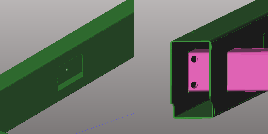 On the left the pocket for tube D and on the right tube E inserted in the tube B.
Please note that the tube E is appropriately cut so that it would rest on the opposite surface of the tube B after insertion. In this way, the position of tube B in the horizontal direction is automatically defined. If one does not want to have that extra length of the tube for weight of cost limitations, with ArTube one can program a line marking or an arrow marking to define the insertion level on tube E and define its horizontal position.
The other way to modify this joint is to use “slot and tab” method as shown in the following images:
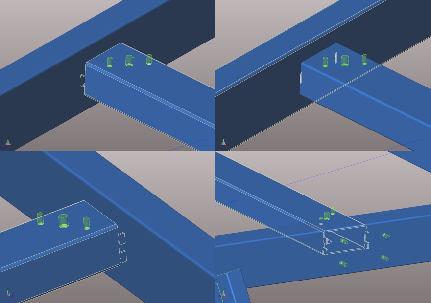 Connection between parts of a tubular frame made with “slot and tabs” functionality.
The slot and tab concept can also be used to guarantee correct assembly by having different number of tabs on the two ends of the tube as shown in the following image.
 “Slot and tab” function used to guarantee correct parts assembly on a tubular frame fabrication.
The same result can also be achieved by having the same number of tabs on the two ends but in different vertical positions.
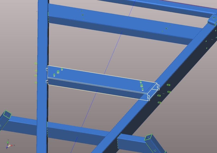
The “tab and slot” functionality can be really helpful even on parts different from tubes, as for example the C-shaped bracket shown on the picture below that has to be welded onto the tube B.
 C-Shaped bracket modeled on tubular frame component with Artube.
With the conventional manufacturing process, one would have to mark the position where the bracket needs to be welded, then place the bracket in position, fix it with a clamp and then weld it.
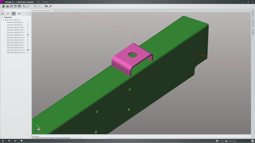
With ArTube these steps can be simplified by creating four teeth on the bracket and corresponding slots on the tube B as shown below:
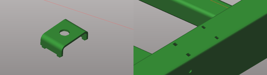 C-shaped bracket with tabs and relative tube with slots for assembly.
With the slots, the position of the bracket is defined and with the teeth the need for clamping is eliminated.
Now you are ready to cut, assemble and weld your frame with ease and in a very short time, whether you want to make one or thousands of those.
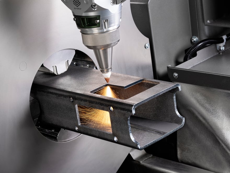 Laser cutting of a tubular frame component with LT FIBER EVO Lasertube.
Ideas never end with Artube
Those mentioned here are only some of the ideas that have been put into practice. Artube offers a wide variety of software functionalities that help to improve the assembly and welding of tubular structure.
If only one example of such a structure is to be fabricated, one can probably use the conventional method, spending a lot of time and energy to get the structure made only to have accuracy and aesthetical problems. Imagine how complicated and time consuming it would become if one wants to manufacture multiple structures.
With a Lasertube and Artube, you can get a big advantage even if you need to fabricate only one structure. The advantage is exponentially multiplied as the production quantity increases.