Many tube fabricators use a different programming platform for each machine, which leads to some specific inefficiencies. Connecting two or more processes together using Industry 4.0 technology platforms provides a seamless operation in programming, fabricating, and process validation.
 Many tube fabricators use a different programming platform for each machine, which leads to some specific inefficiencies. Connecting two or more processes together using Industry 4.0 technology platforms provides a seamless operation in programming, fabricating, and process validation.
Optimizing productivity and working efficiently can be at odds with each other, and as manufacturing processes become ever more complex, it can be increasingly difficult to work toward both of these goals. Dealing with multiprocess platforms — laser cutting, bending, and welding, for example — makes the many variables even more challenging to manage. Where possible, using a single software platform to program a variety of machines can be a big boost to productivity and efficiency.
Bridging the gap between tube lasers and tube benders traditionally has been cumbersome. The crux of the matter was a lack of viable technology platform linking the two processes, starting at the product design and programming phase. Managing these processes through the traditional method requires generating NC programs for the tube laser and tube bender on two separate platforms.
Without any shared data, required part corrections and compensations are handled manually, using a trial-and-error approach. This can take several iterations, especially as the parts become more complex.
This sacrifices productivity and significantly increases manufacturing costs. Besides part complexity, increased part changeovers (as in a high-mix production environment) also make it more challenging, as the measurement and manual correction steps must be repeated several times for each process and each material variation.
Break Out the Slide Rule
Before the bending process begins, the programmers or machine operators have to calculate or estimate the initial straight length of the tube manually for the cutting process. The bending process can cause elongation, radial growth, and springback on the workpiece. These, in turn, affect the part’s final dimensions and location features and pre-processed holes. As a tube or pipe is bent, the exterior wall stretches and thins at the tangent point of the bend; simultaneously, the interior wall becomes thicker and more compressed.
Therefore, understanding and managing the degree of physical deformation is important in achieving the desired part quality. However, part complexity and material characteristics make it challenging to gauge the exact effect of bending on the workpiece using only manual calculations. With the traditional, manual method, the machine operator must measure the bent part and hole locations after bending and adjust the starting part length and hole locations.

This process might have to be repeated several times before the desired results are achieved. Additionally, the process’s lack of repeatability, depending on the bending operation, makes this task even more cumbersome.
In general, as the radius becomes tighter, the material stretches more. In some cases, material selection is dictated by the expected level of elongation. For example, stainless steel has a higher maximum elongation than other grades of steel. However, with traditional methods, the expected level of elongation is mostly calculated with rules of thumb and corrections performed by trial and error, especially when the part geometry is more complex. Thus, it might be necessary to repeat the calculation several times before achieving the desired result.
To minimize the degree of deviation, market demands have made it mandatory for manufacturers to find advanced methods for effective management of all the process variables between part design and manufactured parts or assemblies.
Find out how to solve the main tube bending problems with the right programming software.
Break Out the Software
Technological advancements in machine-to-machine communication, industrial internet of things (iIoT) systems, and machine learning have created a method for assemblies or single part models to be imported directly into the tube laser software and managed within the same environment across multiprocess platforms. This method removes the manual calculations, rules of thumb, and guesswork that often lead to trial-and-error corrections.
OLP, CAD/CAM
To start the process, a 3D model of a bent tube or frame assembly is imported directly into the tube laser software. The software’s CAD module generates the tube’s theoretical straight length.
The offline programming (OLP) software uses a dynamic feature-extraction algorithm to identify the size and position of bending segments and unfolds the bent model from a straight tube automatically, while maintaining part properties and features according to the theoretical design. Then software generates two NC programs: one for the laser and another one for the tube bender, which can be transferred over a local area network or a wide area network to both machines. This eliminates the need for the machine operator or programmer to calculate the bending coordinates manually and input them into the tube bender control or to import the 3D part model into the tube bender and determine the bending coordinates again.
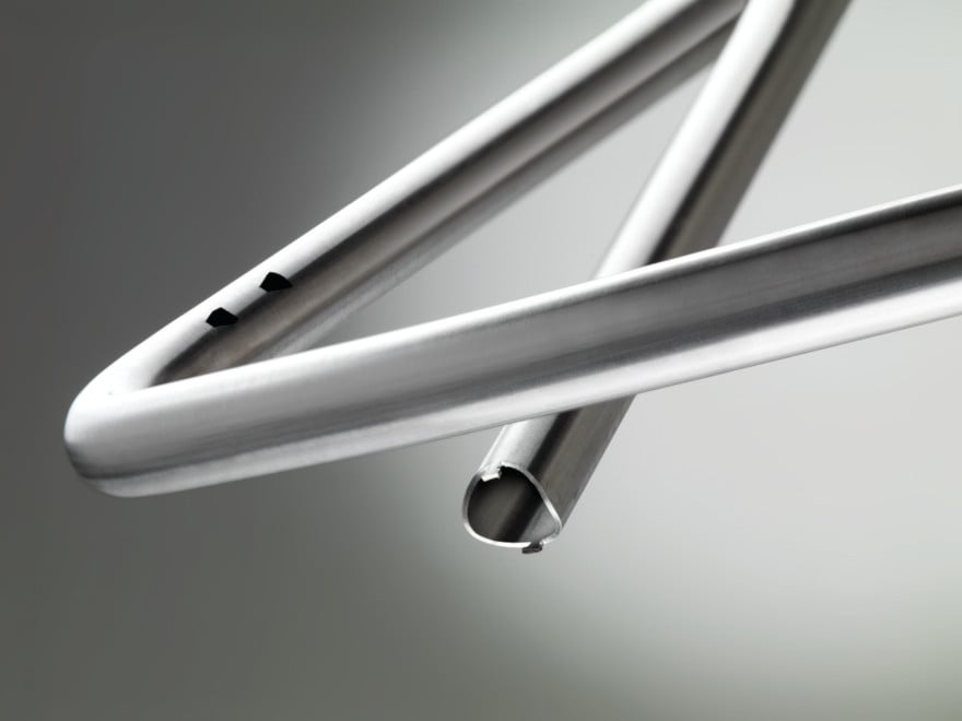
 Two opposing holes are incorporated into the drawing of this component. A typical laser can make these features with a dimensional accuracy and tolerance that is hard to match.
Furthermore, advanced systems provide a powerful method to close the communication loop between the two processes by fetching bending compensation data from the bender and making the data available for the laser cutting process, either at the machine or at the OLP software level. The user can choose to access the information at the laser machine or at the OLP software, based on the production requirements.
Compensation
The bending software dynamically calculates springback, radial growth, and elongation, based on a data table that is saved when setting up new tooling. Based on this data, the bending compensation module provides an accurate initial straight length of the tube and corrects the critical bend points, according to the theoretical part dimensions without the need to bend the part physically.
Integrated processes using Industry 4.0 platforms have a subtle but important advantage over traditional systems. Manual calculations can be eliminated through integrated systems. For instance, traditional springback compensation methods consider the bend angle only; they don’t account for radial growth and elongation.
The compensation data is transferred back to the laser (online or offline) via the network, giving the operator the option to choose to implement it or not. Before the cutting process begins, the hole locations are offset by the amount of the calculated stretch in relation to the bend location, and the length of the part also is adjusted to match the dimensions specified by the tube bender. This allows the cutting machine to make the correct initial tube length and hole locations for bending and ensures that the first bent part is accurate. The compensation data also can be transferred to the tube laser OLP software. The programmer can apply the compensation information to edit the part features at the CAM level automatically, without affecting the theoretical part design, and transfer the new program to the machine for cutting.
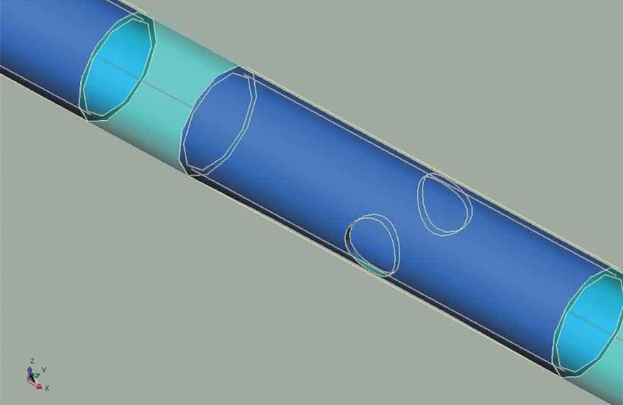
.jpg?width=880&name=industry-40-platforms-provide-an-integrated-process-for-making-tub%20(1).jpg) Regardless of a laser’s ability to make the holes with nearly perfect dimensions, the finished part has value only if the hole locations are accurate. This image shows the original hole location from the print (in green) and the proper location for cutting the holes (dotted lines). After the part is bent, the holes represented by the dotted lines will align with the holes represented by the green lines and the part will function as intended.
Regardless of a laser’s ability to make the holes with nearly perfect dimensions, the finished part has value only if the hole locations are accurate. This image shows the original hole location from the print (in green) and the proper location for cutting the holes (dotted lines). After the part is bent, the holes represented by the dotted lines will align with the holes represented by the green lines and the part will function as intended.
Wrapping It Up
In addition to increasing manufacturing efficiency and significantly reducing labor and material costs, Industry 4.0 platforms and integrated systems can free up manufacturing personnel so that their efforts are better spent in improving other processes and creating efficient methods. This technology platform efficiently eliminates the repetitive, the iterative, and the mundane, leaving personnel to create, improve, and validate systems.
Leave it to software and related systems to deal with complex part geometries, stringent quality requirements, and demanding production schedules. Besides bridging the gap between the manufacturing processes, Industry 4.0 provides a versatile platform which could help fabricators integrate all of their production systems, material handling, and logistics.
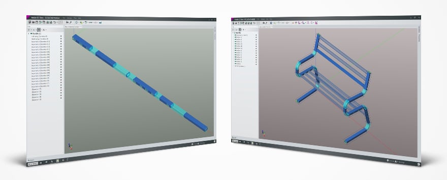 A bent tube or frame 3D Model is imported directly into the tube laser software through the CAD module, which generates the tube’s relative theoretical straight part.
Author: Misgana Mulat, regional sales manager for BLM GROUP USA, 46850 Cartier Drive, Novi, MI 48377, 248-560-0080
Source: The Tube & Pipe journal